An ER diagram is a visual representation of the entities, attributes, and relationships between them in a database. Entities represent real-world objects or concepts that are important to the business or organization. For example, in a university database, entities might include students, courses, and instructors. Attributes are the characteristics of an entity. For example, the attributes of a student entity might include their name, student ID, and email address.
Components of ER Diagram:
This model is based on three basic concepts:
- Entities
- Attributes
- Relationships
Entity:
In a database schema or ER diagram, an entity is represented by a rectangle with its name written inside. The attributes or properties of the entity are listed inside the rectangle, and a unique identifier or primary key is specified to distinguish one instance of the entity from another. Example:

In an Entity-Relationship (ER) diagram, a weak entity is represented by a double rectangular box. The double box represents the weak entity, and it is usually connected to a related strong entity using a diamond-shaped connector.
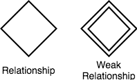
Relationships between Entities – Weak and Strong
- A strong relationship is one where the existence of one entity is dependent on the existence of another entity.
- On the other hand, a weak relationship is one where the existence of one entity is not dependent on the existence of another entity.
Attributes for any Entity:
In Entity-Relationship (ER) diagrams, an ellipse is used to represent an attribute of an entity. The ellipse is connected to the entity using a line, and the name of the attribute is usually placed inside the ellipse.

Attributes are of various types, following are given below:
- Key Attribute: The attribute name inside the Ellipse is underlined to signify a Key attribute.
- Derived Attribute: Attributed is calculated or otherwise derived from another attribute, such as age from a birthdate.
- Multivalued Attribute: More than one attribute value is denoted, such as multiple phone numbers for a person.
- Composite Attribute: A composite attribute is an attribute, which also has attributes.

where,
- Address is a simple attribute.
- Student ID prime attribute
- Name is a composite attribute as it has more attributes such as first name, last name, etc.
- Age is a derived attribute (from Date of Birth)
- Course is a multivalued attribute.
- Student is an entity.
ER Diagram: Relationship
Entities can have one of three different types of relationships.
- Binary Relationship
- Recursive Relationship
- Ternary Relationship
Binary Relationship:
A binary relationship is a relationship between two entities. For example, a customer places an order, or an employee manages a project. Binary relationships can be of the one-to-one, one-to-many, or many-to-many type.
- One-to-One (1:1) Relationship: In a one-to-one relationship, one entity is associated with exactly one instance of another entity. For example, one person can have only one passport.
- One-to-Many (1:N) Relationship: In a one-to-many relationship, one entity is associated with many instances of another entity. For example, one customer can have many orders.
- Many-to-Many (N:M) Relationship: In a many-to-many relationship, many instances of one entity are associated with many instances of another entity. For example, many students can be enrolled in many courses.

Recursive Relationship:
A recursive relationship is a relationship between an entity and itself. This can occur when an entity has a hierarchical structure, such as an organizational chart. For example, an employee can supervise other employees, and can also be managed by another employee.

Ternary Relationship:
A ternary relationship is a relationship between three entities. For example, a customer can place an order for a product that is supplied by a supplier. Ternary relationships are less common than binary relationships, but they can be used to model more complex scenarios where multiple entities are involved.
Note: also read about Basic Concepts of ER Model
Follow Me
Please follow me to read my latest post on programming and technology if you like my post.
Leave a Reply
You must be logged in to post a comment.